3D Model
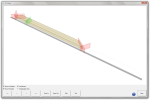
The 3D Model window shows a realistic 3D representation of a specific member or of the optimised layout of a specific board.
 Access
To open the 3D Model window, do the following:
- Right-click a member in the Member List or Optimised tab.
- Select 3D Model... from the context menu.
Note: If opened from the Member List tab, the 3D Model window will show a representation of the selected member only. If opened from the Optimised tab, the full composition of the board or stack formation containing the selected member will be shown.
 Legend
The following elements can be present on the 3D model:
|
|
Board footprint |
|
Fenceline |
|
|
|
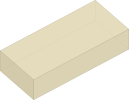
Member (light brown) |
|
Non-shared regular cut (red plane) |
|
|
|
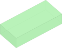
Offcut (green) |
|
Shared cut (green plane) |
|
|
|
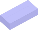
Reuse (blue) |
|
Special cut (purple plane) |
|
Notes:The board footprint is only visible when opening the 3D model from the Optimised tab.you can show or hide the fenceline and cutting planes by using the checkboxes in the lower left corner of the window.
 Controls
|
|
Hold down the right-click button and move the mouse to rotate the model. |
|
|
Click to jump to the previous member end. |
|
|
Click to jump to the next member end. |
|
← or |
Press the left arrow key on the keyboard or click this button to move the camera one step to the left. |
|
→ or |
Press the right arrow key on the keyboard or click this button to move the camera one step to the right. |
|
|
Scroll up with the mouse wheel or click this button to move the camera closer to the board. |
|
|
Scroll down with the mouse wheel or click this button to move the camera farther from the board. |
|
|
Click to switch to the side view. |
|
|
Click to switch to the top view. |


 or
or 
 or
or 

